Uses timer to set interval between ADC single conversions that are then sent as stream messages to host. More...
#include "asc_exception.h"#include "asc_helpers.h"#include "ascii_serial_com.h"#include "ascii_serial_com_device.h"#include "ascii_serial_com_register_pointers.h"#include "avr/avr_uart.h"#include "circular_buffer.h"#include "millisec_timer.h"#include <avr/interrupt.h>#include <avr/io.h>#include <util/atomic.h>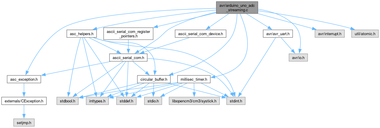
Go to the source code of this file.
Macros | |
| #define | F_CPU 16000000L |
| #define | BAUD 9600 |
| #define | MYUBRR (F_CPU / 16 / BAUD - 1) |
| #define | UART_NO 0 |
| #define | have_finished_ADC_conversion (!(ADCSRA & (1 << ADSC))) |
| #define | nRegs 10 |
Functions | |
| DECLARE_ASC_DEVICE_W_REGISTER_POINTERS () CEXCEPTION_T e | |
| int | main (void) |
| def_usart_isr_push_rx_to_circ_buf (USART_RX_vect, UDR0, &extraInputBuffer) MILLISEC_TIMER_AVR_TIMER0_ISR | |
Variables | |
| bool | have_started_ADC_conversion = false |
| millisec_timer | adc_timer |
| uint32_t | adc_sample_period_ms = 1000 |
| volatile REGTYPE * | register_map [nRegs] |
| Register Map. | |
| REGTYPE | register_write_masks [nRegs] |
| Write masks for register_map. | |
| uint16_t | nExceptions |
Detailed Description
Uses timer to set interval between ADC single conversions that are then sent as stream messages to host.
On receiving 'n' message, begins streaming ADC values to host (by default the ADC is connected to ground) Stops when 'f' message is received.
ADC channel selection and time between ADC conversions are configurable with registers.
You can also turn on and off the user LED with register 0, bit 5
Register map is documented at register_map
Definition in file arduino_uno_adc_streaming.c.
Macro Definition Documentation
◆ BAUD
| #define BAUD 9600 |
Definition at line 32 of file arduino_uno_adc_streaming.c.
◆ F_CPU
| #define F_CPU 16000000L |
Definition at line 31 of file arduino_uno_adc_streaming.c.
◆ have_finished_ADC_conversion
| #define have_finished_ADC_conversion (!(ADCSRA & (1 << ADSC))) |
Definition at line 37 of file arduino_uno_adc_streaming.c.
◆ MYUBRR
| #define MYUBRR (F_CPU / 16 / BAUD - 1) |
Definition at line 33 of file arduino_uno_adc_streaming.c.
◆ nRegs
| #define nRegs 10 |
Definition at line 42 of file arduino_uno_adc_streaming.c.
◆ UART_NO
| #define UART_NO 0 |
Definition at line 34 of file arduino_uno_adc_streaming.c.
Function Documentation
◆ DECLARE_ASC_DEVICE_W_REGISTER_POINTERS()
| DECLARE_ASC_DEVICE_W_REGISTER_POINTERS | ( | ) |
Definition at line 155 of file stm32f091nucleo64_adc_streaming.c.
◆ main()
| int main | ( | void | ) |
Definition at line 108 of file arduino_uno_adc_streaming.c.
Variable Documentation
◆ adc_sample_period_ms
| uint32_t adc_sample_period_ms = 1000 |
Definition at line 40 of file arduino_uno_adc_streaming.c.
◆ adc_timer
| millisec_timer adc_timer |
Definition at line 39 of file arduino_uno_adc_streaming.c.
◆ have_started_ADC_conversion
| bool have_started_ADC_conversion = false |
Definition at line 36 of file arduino_uno_adc_streaming.c.
◆ nExceptions
| uint16_t nExceptions |
Definition at line 107 of file arduino_uno_adc_streaming.c.
◆ register_map
| volatile REGTYPE* register_map[nRegs] |
Register Map.
Lower byte of the 16 bit variables is in lower register number
| Register Number | Description | r/w | Default |
|---|---|---|---|
| 0 | PORTB, bit 5 is LED | r, bit 5 is w | 0 |
| 1 | ADMUX | r, lower 4 bits w | 0x4F (ground) |
| 2 | adc_sample_period_ms lowest 8 bits | r/w | 0xe8 (1000) |
| 3 | adc_sample_period_ms bits 8-15 | r/w | 0x03 |
| 4 | adc_sample_period_ms bits 16-23 | r/w | 0 |
| 5 | adc_sample_period_ms bits 24-21 | r/w | 0 |
| 6 | MILLISEC_TIMER_NOW lowest 8 bits | r | counting |
| 7 | MILLISEC_TIMER_NOW bits 8-15 | r | counting |
| 8 | MILLISEC_TIMER_NOW bits 16-23 | r | counting |
| 9 | MILLISEC_TIMER_NOW bits 24-21 | r | counting |
ADMUX: the upper half of the register is the read only ADC reference selection. The bottom 4 bits are r/w and are the channel selection. values of 0-7 select the ADC channel to read from and 0xF is GND. Don't write any values besides 0-7 and 0xF, as it could cause issues.
adc_sample_period_ms: the time between ADC conversion in milliseconds. default: 1000 ms = 1 s
- See also
- register_write_masks
Definition at line 72 of file arduino_uno_adc_streaming.c.
◆ register_write_masks
| REGTYPE register_write_masks[nRegs] |
Write masks for register_map.
These define whether the given register in register_map is writable or not
Definition at line 90 of file arduino_uno_adc_streaming.c.