Streams ADC data from pin A0 (happens to be labelled A0 on the Arduino connector of nucleo-f091rc board) More...
#include <libopencm3/cm3/cortex.h>#include <libopencm3/cm3/nvic.h>#include <libopencm3/stm32/adc.h>#include <libopencm3/stm32/dac.h>#include <libopencm3/stm32/gpio.h>#include <libopencm3/stm32/rcc.h>#include <libopencm3/stm32/timer.h>#include <libopencm3/stm32/usart.h>#include "arm/stm_usart.h"#include "asc_exception.h"#include "asc_helpers.h"#include "ascii_serial_com.h"#include "ascii_serial_com_device.h"#include "ascii_serial_com_register_pointers.h"#include "circular_buffer.h"#include "millisec_timer.h"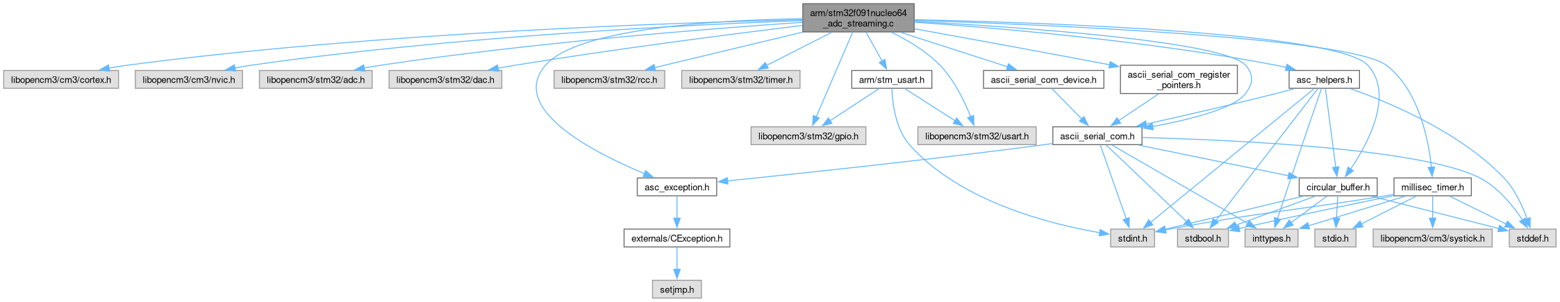
Go to the source code of this file.
Macros | |
| #define | ASC_USART_NO 2 |
| #define | ASC_USART USART2 |
| #define | PORT_LED GPIOA |
| #define | PIN_LED GPIO5 |
| #define | RCC_GPIO_LED RCC_GPIOA |
| #define | DAC_RESET_TIME_MS 500 |
| #define | nRegs 10 |
| #define | nChans 1 |
Functions | |
| DECLARE_ASC_DEVICE_W_REGISTER_POINTERS () static void gpio_setup(void) | |
| static void | adc_setup (void) |
| static void | dac_setup (void) |
| int | main (void) |
Variables | |
| CEXCEPTION_T | e |
| uint16_t | nExceptions |
| MILLISEC_TIMER_SYSTICK_IT | |
| millisec_timer | adc_timer |
| uint32_t | adc_sample_period_ms = 1000 |
| uint32_t | adc_n_overruns = 0 |
| millisec_timer | dac_reset_timer |
| uint32_t | optionFlags = 0 |
| volatile REGTYPE * | register_map [nRegs] |
| Register Map. | |
| REGTYPE | register_write_masks [nRegs] |
| Write masks for register_map. | |
| uint32_t | counter = 0 |
| uint8_t | tmp_byte = 0 |
Detailed Description
Streams ADC data from pin A0 (happens to be labelled A0 on the Arduino connector of nucleo-f091rc board)
The time between ADC conversions is set in register 6, in milliseconds.
Through changing option flag, can instead stream a 32 bit counter
DAC channel 1 (A4 and Arduino A2 on board) is also enabled and may be changed by writing to register 3. Period between DAC conversions is configurable as is trinagle/noise generation.
A register write can also turn on/off the LED
Register map is documented at register_map
Definition in file stm32f091nucleo64_adc_streaming.c.
Macro Definition Documentation
◆ ASC_USART
| #define ASC_USART USART2 |
Definition at line 40 of file stm32f091nucleo64_adc_streaming.c.
◆ ASC_USART_NO
| #define ASC_USART_NO 2 |
Definition at line 39 of file stm32f091nucleo64_adc_streaming.c.
◆ DAC_RESET_TIME_MS
| #define DAC_RESET_TIME_MS 500 |
Definition at line 56 of file stm32f091nucleo64_adc_streaming.c.
◆ nRegs
| #define nRegs 10 |
Definition at line 62 of file stm32f091nucleo64_adc_streaming.c.
◆ PIN_LED
| #define PIN_LED GPIO5 |
Definition at line 43 of file stm32f091nucleo64_adc_streaming.c.
◆ PORT_LED
| #define PORT_LED GPIOA |
Definition at line 42 of file stm32f091nucleo64_adc_streaming.c.
◆ RCC_GPIO_LED
| #define RCC_GPIO_LED RCC_GPIOA |
Definition at line 44 of file stm32f091nucleo64_adc_streaming.c.
Function Documentation
◆ adc_setup()
|
static |
Definition at line 165 of file stm32f091nucleo64_adc_streaming.c.
◆ dac_setup()
|
static |
Definition at line 195 of file stm32f091nucleo64_adc_streaming.c.
◆ DECLARE_ASC_DEVICE_W_REGISTER_POINTERS()
| DECLARE_ASC_DEVICE_W_REGISTER_POINTERS | ( | ) |
Definition at line 155 of file stm32f091nucleo64_adc_streaming.c.
◆ main()
| int main | ( | void | ) |
Definition at line 223 of file stm32f091nucleo64_adc_streaming.c.
Variable Documentation
◆ adc_n_overruns
| uint32_t adc_n_overruns = 0 |
Definition at line 54 of file stm32f091nucleo64_adc_streaming.c.
◆ adc_sample_period_ms
| uint32_t adc_sample_period_ms = 1000 |
Definition at line 53 of file stm32f091nucleo64_adc_streaming.c.
◆ adc_timer
| millisec_timer adc_timer |
Definition at line 52 of file stm32f091nucleo64_adc_streaming.c.
◆ counter
| uint32_t counter = 0 |
Definition at line 153 of file stm32f091nucleo64_adc_streaming.c.
◆ dac_reset_timer
| millisec_timer dac_reset_timer |
Definition at line 55 of file stm32f091nucleo64_adc_streaming.c.
◆ e
| CEXCEPTION_T e |
Definition at line 48 of file stm32f091nucleo64_adc_streaming.c.
◆ MILLISEC_TIMER_SYSTICK_IT
| MILLISEC_TIMER_SYSTICK_IT |
Definition at line 51 of file stm32f091nucleo64_adc_streaming.c.
◆ nExceptions
| uint16_t nExceptions |
Definition at line 49 of file stm32f091nucleo64_adc_streaming.c.
◆ optionFlags
| uint32_t optionFlags = 0 |
Definition at line 60 of file stm32f091nucleo64_adc_streaming.c.
◆ register_map
| volatile REGTYPE* register_map[nRegs] |
Register Map.
Register Map
| Register Number | Description | r/w |
|---|---|---|
| 0 | PORTA input data register, bit 5 is LED | r |
| 1 | PORTA output data register, bit 5 is LED | r, bit 5 is w |
| 2 | optionFlags: see below | r/w |
| 3 | DAC Channel 1 output val | r, bottom 12 bits w |
| 4 | Reserved for DAC Channel 2, but not implemented | r |
| 5 | Current millisecond_timer value | r |
| 6 | Period between ADC samples in ms * | r/w |
| 7 | Number of times ADC overrun flag has been set | r |
| 8 | Time between DAC conversion in 100 us * | r/w 16 bits |
| 9 | DAC waveform & waveform amplitude sel. * | r, w bits 6-10 |
Option flags
| Big Number | Description |
|---|---|
| 0 | if 0: stream ADC, if 1: stream counter |
| 1 | if 1: disable & re-enable DAC, then reset bit to 0, if 0: nothing |
Register 6: ADC sample period only written to ADC register when 'n' command received
Register 8: default 100, so update every 10 ms
Waveform generation with register 9
Register 9: default 0. Bits 6-7 (start from 0) control waveform generation. 00: disabled, 01: noise, 1x: triangle. Bits 8-11 are amplitude: where the max-min is 2^(n+1)-1, where n is the value (at least for triangle), maxing out at 0b1011=0xB. The triangle starts from reg 3 and goes up to the max-min value programmed, then comes back down. The noise is centered around register 3.
So, write to the register: 0xYZ0, where Y is the amplitude: 0-B, and Z is the waveform type: 0 for none, 1 for nosie, 8 for triangle.
I'd say the noise has an RMS in the region of 10 counts. The mask doesn't change the RMS that much.
It may be necessary to reset the DAC (see option flags) to change the amplitude and/or disable waveform generation
Register 9 examples:
- triangle with max-min = 127: 0b10110000000 = 0x680
- full scale triangle: write 9 0xB80, write 3 0, write 8 3
- noise with large amplitude: 0xB10
- flat, waveform disabled: 0
- See also
- register_write_masks
Definition at line 121 of file stm32f091nucleo64_adc_streaming.c.
◆ register_write_masks
| REGTYPE register_write_masks[nRegs] |
Write masks for register_map.
These define whether the given register in register_map is writable or not
Definition at line 140 of file stm32f091nucleo64_adc_streaming.c.
◆ tmp_byte
| uint8_t tmp_byte = 0 |
Definition at line 222 of file stm32f091nucleo64_adc_streaming.c.