To be used with the timer peripherals on STM32 microcontrollers. More...
#include <libopencm3/stm32/gpio.h>#include <libopencm3/stm32/timer.h>#include <stdint.h>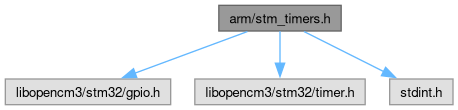
Go to the source code of this file.
Macros | |
| #define | setup_timer_periodic_output_pulse(timer, prescale, period, pulse_length, output, gpio_port, gpio_pin, gpio_af) |
| Initialize a timer to output a periodic pulse on an output pin. | |
| #define | setup_timer_capture_pwm_input(timer, prescale, max_timer_counts, input, gpio_port, gpio_pin, gpio_af) |
| Initialize a timer to capture periodic pulses on an input pin. | |
Detailed Description
To be used with the timer peripherals on STM32 microcontrollers.
Definition in file stm_timers.h.
Macro Definition Documentation
◆ setup_timer_capture_pwm_input
| #define setup_timer_capture_pwm_input | ( | timer, | |
| prescale, | |||
| max_timer_counts, | |||
| input, | |||
| gpio_port, | |||
| gpio_pin, | |||
| gpio_af ) |
Initialize a timer to capture periodic pulses on an input pin.
This really just sets up a timer for PWM input capture
Usage
The pulse period should be available in TIM_CCR1(<timer>) in timer ticks
The pulse length should be available in TIM_CCR2(<timer>) in timer ticks
So duty cycle is TIM_CCR2(<timer>) / TIM_CCR1(<timer>)
Polling: bool flag = timer_get_flag(<timer>,TIM_SR_CC1IF);, if true read out TIM_CCR2(<timer>) and TIM_CCR1(<timer>), then check the overcapture bits: timer_get_flag(<timer>,TIM_SR_CC1OF) && timer_get_flag(<timer>,TIM_SR_CC2OF).
Interrupt: Setup the interrupt on CC1: timer_enable_irq(<timer>,TIM_DIER_CC1IE), then in the handler read out both CCRs and then check the overcapture bits: timer_get_flag(<timer>,TIM_SR_CC1OF) && timer_get_flag(<timer>,TIM_SR_CC2OF)
DMA: ?
If overcapture happens, you have to clear the flag with timer_clear_flag(<timer>,TIM_SR_CC1OF) or timer_clear_flag(<timer>,TIM_SR_CC2OF).
Notes
The user must setup the peripheral clocks for both this timer and the input port.
The user must enable the counter when ready with: timer_enable_counter(<timer>);
Uses input compare channels 1 and 2, so timer must have 2 IC units!
This macro takes care of setting up the GPIO pin.
Sets timer in: upcount, edge-aligned, not one-pulse mode, using the un-divided peripheral clock as input to the prescaler. This should be available on all general-purpose timers.
Registers Relevant to Ascii-Serial-Com
TIM_PSC(<timer>): which should be set to the prescaler value in peripheral clock ticks
TIM_CCR1(<timer>): read the pulse period in timer ticks
TIM_CCR2(<timer>): read the pulse length in timer ticks
Parameters
timer: the timer you want to use like TIM2
prescale: the number of peripher clock ticks between timer ticks, uint32_t (but only ever 16 bit)
max_timer_counts: you probably want 0xFFFF for 16 bit counters and 0xFFFFFFFF for 32 bit ones.
input: which input compare input: TIM_IC_IN_TI1, TIM_IC_IN_TI2, TIM_IC_IN_TI3 or TIM_IC_IN_TI4 (don't quote; some not avaiable on all timers)
gpio_port: GPIOA, GPIOB, ... (must match input)
gpio_pin: GPIO0, GPIO1, ... (must match input)
gpio_af: alternate function for the given pin/port and input, e.g. GPIO_AF0, GPIO_AF1, ...
Definition at line 156 of file stm_timers.h.
◆ setup_timer_periodic_output_pulse
| #define setup_timer_periodic_output_pulse | ( | timer, | |
| prescale, | |||
| period, | |||
| pulse_length, | |||
| output, | |||
| gpio_port, | |||
| gpio_pin, | |||
| gpio_af ) |
Initialize a timer to output a periodic pulse on an output pin.
This really just sets up a timer in edge-aligned PWM mode.
Notes
The user must setup the peripheral clocks for both this timer and the output port.
The user must enable the counter when ready with: timer_enable_counter(<timer>);
This macro takes care of setting up the GPIO pin.
Uses output compare unit 1 on the timer. Make sure this is available on the timer.
Sets timer in: upcount, edge-aligned, not one-pulse mode, using the un-divided peripheral clock as input to the prescaler. This should be available on all general-purpose timers.
Registers Relevant to Ascii-Serial-Com
TIM_ARR(<timer>): which should be set to period in timer ticks
TIM_CCR1(<timer>): which should be set to pulse_length in timer ticks
TIM_PSC(<timer>): which should be set to the prescaler value in peripheral clock ticks
Parameters
timer: the timer you want to use like TIM2
prescale: the number of peripher clock ticks between timer ticks, uint32_t (but only ever 16 bit)
period: The number of timer ticks between pulse rising edges, uint32_t
pulse_length: length of pulse in timer ticks, uint32_t
output: the output compare output to use: TIM_OC1, TIM_OC2, TIM_OC3, TIM_OC4 (availability depends on timer)
gpio_port: GPIOA, GPIOB, ... (must match output)
gpio_pin: GPIO0, GPIO1, ... (must match output)
gpio_af: alternate function for the given pin/port and output, e.g. GPIO_AF0, GPIO_AF1, ...
Definition at line 66 of file stm_timers.h.